Power attenuators for the FT-817
When you participate in contests, you probably noticed, that when the propagation is very good to extremely good, signals can be very strong. Signals can peak to S9+10 dB or even S9+20 dB. When signals are S9, I can answer with 1 watt (in CW).
When signals are 10 dB stronger than S9, my signal will also be 10 dB stronger, so I can reduce my power by 10 dB and still be heard. To go below the lowest power of 500 mW of the Yaesu FT-817, I built two accurate pi attenuators for 50 ohm in cascade. One of 10 dB and one of 20 dB.
Attenuators
The power of the FT-817 is 5W, 2.5 W, 1W or 500 mW. By using one of the two attenuators and the adjustable power of the FT-817, the power to the antenna can be adjusted from 5 W down to 5 milliwatt, in steps of 3 or 4 dB, as shown in the table.
FT-817 with attenuator
A 10 dB attenuator reduces the power to 1/10th. For instance, 500 mW will be reduced to 50 mW. A 20 dB attenuator will reduce the power to 1/100th. Calculating the power behind the attenuator, is very simple. Just move the decimal point one place to the left for 10 dB and 2 places for 20 dB. This simple calculation, allows me to immediately note the power after each QSO.
Please note that the tuner (transmatch) is placed behind the attenuator. I tune carefully, with the attenuator is on bypass (0 dB), to get a SWR of exactly 1:1 on the SWR-meter of the FT-817, so the input of the tuner shows 50 ohms. So when I later use the attenuator, the attenuator is terminated with 50 ohms and will give the right attenuation.
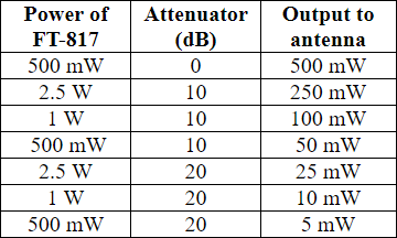
Table FT-817 with attenuator
Working with very low power
When I use an attenuator, I always answer a CQ. Before I answer, I quickly adjust the power. When the S-meter goes up, the power goes down. In CW QSO’s with the lowest possible power, I increase my power with a step of 3 or 4 dB, when I am sure that my call is not heard. When I use the attenuator, I always listen and transmit through the attenuator. In my log I always note my power in each QSO.
Power Attenuators for CW with the FT-817
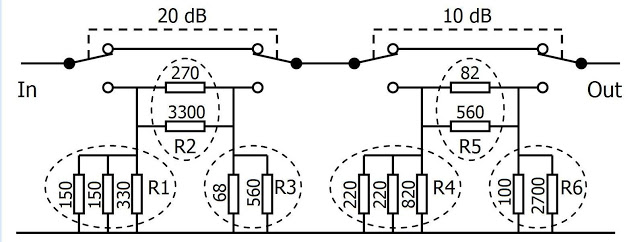
The attenuators shown here, can be built with good available carbon, or other induction free resistors, from the E12-series. The resistors R1 to R6 have a value, that is not available in the E12-series. But by placing two resistors from the E12-series in parallel, we can make any value we want. I use 3 resistors in parallel, to form the compound resistors R1 and R4. In R1and R4, the power is distributed over the two resistors with the lowest value. The resistor with the highest value is added to arrive on required value.
The maximum power to the attenuators is 2.5 W, to make 250 mW, using the 10 dB attenuator or to make 25 mW, using the 20 dB attenuator, as shown in the table. I use the attenuators exclusively for CW. Since the average power of a CW signal is about half of the continuous power, the attenuators must be able to dissipate a power of at least 1.25 W.
In order to use a not to many resistors, I chose for resistors of ½ watt, in stead of ¼ watt.
Power Attenuators for the FT-817
The continuous maximum input power of the 20 dB attenuator is 1.5 W and 1.7 W for the 10 dB attenuator, with resistors or ½ watt. This power will be doubled with 1 W resistors.
Because the attenuator of 10 dB and 20 dB can be switched independently, they are both designed for about the same maximum input power. Each attenuator must have a switch, so the attenuators can be switched ”on” or ”off” at any moment, for instance for tuning.
The power attenuators are asymmetrical. The input of the attenuator is connected to the set and the output to the tuner. Input and output of asymmetrical attenuators, should not be reversed.
This will destroy the attenuator, since R3 and R6 can not dissipate more than about ½ watt. The attenuators will be accurate, since the resistors are more accurate than 5%, when built with resistors of 5%.
The use of the attenuators is not restricted to CW. You can also use SSB, PSK or WSPR. With a power of 1W from the FT-817 in WSPR, you can make 100 mW or 10 mW, using the 10 dB or 20 dB attenuator. You can even make 1 mW by using both attenuators.
QRSS and QRPp is an excellent combination. Just see how low you can go.
Building the attenuators
The leads of the compound resistors can be twisted together before soldering. The resistors R1 and R3 are connected between a point on the switch and the ground. The resistor R2 is connected between two points of the switch. The same goes for R4, R6 and for R5.
By placing the resistors in parallel, forming the compound resistors R1 to R6, the layout of the attenuators is very simple. By this unique feature, it is not necessary to use a printed circuit board.
Attenuator 20 dB 10dB Layout
After construction
It is great fun to make QSO’s with 50 mW or less. An attenuator of 10 dB and an attenuator of 20 dB between the set and the tuner, will give you a lot of fun. When a signal is S9 + 10 dB, or higher, QSO’s can be made with 50 mW or sometimes even 25 mW. The propagation must be very good to extremely good to use the attenuators. When the S-meter goes up, just try a lower power. From my own experience I know that in each contest, QSO’s can be made with very low power.
Power Attenuator Calculator
If you want to design your own Power Attenuator, for 20 dB, 10 dB or 3 dB, for a higher maximum input power or built with smaller ¼ W resistors, please feel free to download and use the excellent PA1B Power Attenuator Calculator.
This spreadsheet in Excel can be found on my website and on my page on QRZ.com.
More, interesting info on the use of attenuators, can be found on my website:
https://a29.veron.nl/pa1b.htm