PA1B Attenuators
Attenuator design
This attenuator is a Pi-type, 50 ohm attenuator for 10 dB.
The resistors R1 at the input and R3 at the output of the attenuator, always have the same value.
In a 10 dB attenuator they both must be 96.25 ohm. The resistor R2 has a value of 71.15 ohm.
The values of 96.25 ohm and 71.15 ohm are not available in the E12-series.
But luckily any resistor value can be made with great accuracy, by placing two resistor of the E12-series in parallel.
Precise resistor values for a very accurate 10 dB attenuator
You can make any resistor value you want, with two resistors from the E12-series in parallel,
A very accurate 10 dB attenuator
Accurate attenuators can be built with good available resistors from the E12-series.
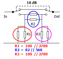
This very accurate 10 dB attenuator is built with 6 resistors. The resistors R1, R2 and R3 are compound resistors and are each formed by two resistors, from the E12-series in parallel.
The resistor R1 and R3 have a wanted value of 96.25 ohm and are both formed by a resistor of 100 ohm and a resistor of 2700 ohm in parallel.
The resistor R2 has a wanted value of 71.15 ohm and is formed by a resistor of 82 ohm and a resistor of 560 ohm in parallel.
Accurate 10 dB attenuator
Very accurate 10 dB attenuator
A very accurate attenuator must be built with 6 resistors of the E12-series.
To make a very precise combination of resistors in parallel, I take the next higher value in the E12-series. The resistor of 100 ohm is chosen, because it is the next value in the E12-series, that is higher than the wanted value of 96.25 ohm. The second resistor in parallel is 2700 ohm. This combination comes very close to the wanted value of 96.25 ohm.
The resistor of 71.15 ohm is formed by a resistor of 82 ohm, parallel to a resistor of 560 ohm.
Accuracy
The accuracy of the individual resistors is always better than 5%. All resistors that I have measured with the ohm meter, while building several attenuators, showed a accuracy of 1.5 % or better.
The combination of each two resistors in parallel, shows an accuracy of 2% or better.
The attenuators built with 6 resistors are very accurate.
10 dB power attenuators
The 10 dB attenuators shown here, are all built with good available 1/4 W resistors of the E12-series. Each of the 4 attenuators is designed for a different value of input power. They cover the power spectrum from 500 mW to 5 watts. The higher the input power the more resistors are needed.
Please notice that if you unleash the maximum power on an attenuator with no cooling, the resistors will easily become (very) hot in a short while. This can reduce the accuracy of the attenuator and can can shorten the life span.
10 dB Attenuator
0.5 W with resistors of 1 W
10 dB Attenuator
1.6 W with resistors of 1 W
10 dB Attenuator
2.8 W with resistors of 1 W
10 dB Attenuator
5 W with resistors of 1 W
With 13 resistors the attenuator is good for 2.8 W (Nominal power 0.7 W or 1.4 W in CW) Built with a total of 20 inexpensive resistors the attenuator can handle a maximum input power of 5 W or a nominal power of 1.25 W.
The resistors will get warm
Tjeerd “Gose” PA3GNZ was inspired by this page about attenuators and some additional info about power attenuators, that I sent him. So he designed a 10 dB attenuator, using 2 watt resistors.
Tjeerd uses the attenuator, to reduce the power of his WSPR signal.
He noticed that during the 2 minute transmission period the attenuator gets warm. You can find the drawing of the symmetrical 10 dB attenuator, on the weblog of Tjeerd >>.
Numbers of the resistors
The resistors in the PA1B attenuators are numbered from left to right. Attenuators built with 6 resistors are very accurate.
In the PA1B power attenuators, each number of a resistor, like R1, R2 or R3 refers to two (or more) resistors in parallel.
By placing several resistors in parallel, the attenuator can dissipate more power. The higher the power, the more resistors are used.
PA1B attenuator
Numbered from left to right
Design table for PA1B attenuators
This table give the precise resistor values, that are needed to design accurate PA1B power attenuators for 1 dB, 2 dB, 3 dB, 7 dB, 10 dB and 20 dB.

Design table for attenuators
PA1B Attenuators
Reserve exemplaar. Kan later weg
Attenuator design
This attenuator is a Pi-type, 50 ohm attenuator for 10 dB. It is designed for 50 ohms and must be terminated with 50 ohms, to give the right attenuation. Please notice that the resistors R1 at the input and R3 at the output of the attenuator, always have the same value. In a 10 dB attenuator they both must be 96.25 ohm. The resistor R2 has a value of 71.15 ohm. The attenuators can be switched on or off. With the switch in the lower position the signal will go through the attenuator.
Numbers of the resistors
The resistors in the PA1B attenuators are numbered from left to right. Attenuators built with 6 resistors are very accurate. In the PA1B power attenuators, each number of a resistor, like R1, R2 or R3 refers to two (or more) resistors in parallel. By placing several resistors in parallel, the attenuator can dissipate more power. The higher the power, the more resistors are used.
Design table for PA1B attenuators
This table give the precise resistor values, that are needed to design accurate PA1B power attenuators for 1 dB, 2 dB, 3 dB, 7 dB, 10 dB and 20 dB.
A very accurate 10 dB attenuator
The PA1B attenuators are build with good available resistors from the E12-series. Use carbon resistors or metal film resistors.
This very accurate 10 dB attenuator is built with 6 resistors. The resistors R1, R2 and R3 are compound resistors and are each formed by two resistors, from the E12-series in parallel. The resistor R1 and R3 have a wanted value of 96.25 ohm and are both formed by two resistors in parallel.
To make a precise combination of resistors in parallel, I take the next higher value in the E12-series. The resistor of 100 ohm is chosen, because it is the next value in the E12-series, that is higher than the wanted value of 96.25 ohm. The second resistor in parallel is 2700 ohm. This combination comes very close to the wanted value of 96.25 ohm.
The resistor of 71.15 ohm is formed by a resistor of 82 ohm, parallel to a resistor of 560 ohm.
Accuracy
The accuracy of the individual resistors is always better than 5%. The resistors that I have measured with the ohm meter, before building several attenuators, showed a accuracy of 1.5 % or better. The combination of each two resistors in parallel, showed an accuracy of 2% or better. The attenuators built with 6 resistors are very accurate.
10 dB power attenuators
The 10 dB attenuators shown here, are all built with good available 1/4 W resistors of the E12-series. Each of the 4 attenuators is designed for a diferent value of input power. They cover the power spectrum from 500 mW to 5 watts. The higher the input power the more resistors are needed. Please notice that the power of each attenuator is the maximum power and with no cooling of the resistors, they will easily become hot in a short while.
The basic 10 dB attenuator consists of 6 resistors and is good for a maximum input power of 500 mW – Nominal 125 mW. Built with 9 resistors the attenuator is suitable for 1.6 W. This is a nominal power of 400 mW.
With 13 resistors the attenuator is good for 2.8 W (Nominalpower 0.7 W or 1.4 W in CW) Built with a total of 20 inexpensive resistors the attenuator can handle a maximum input power of 5 W or a nominal power of 1.25 W.
The resistors will get warm
Tjeerd “Gose” PA3GNZ was inspired by this page about attenuators and some additional info about power attenuators, that I sent him. So he designed a 10 dB attenuator, for an input power of 5 watts, using 1 watt resistors. Tjeerd uses the attenuator, to reduce the power of 5 watts, that is coming from the set, to reduce his WSPR signal to 500 mW. He noticed that during the 2 minute transmission period the attenuator gets warm.
You can find the drawing of the symmetrical 10 dB attenuator, for an input power of 5 watts, on the weblog of Tjeerd >>.