Homebrew QRP transceiver for 40 meters HM7
When I started as a HAM on HF, I built my first Rig myself.
This homebrew QRP transceiver comes from “Solid State Design for the radio amateur” page 214…218.
In the 10 years that I used this CW transceiver, I worked many European countries with a power of only 500 milliwatt in many QSO’s and many contest QSO’s on 7 MHz.
I use a symmetrical tuner and an Inverted V, that is fed with twin lead.
I used this transceiver as a homestation and on holiday.
Homebrew, QRPp and CW (Morse code >>) is a fabulous combination.
Schematic
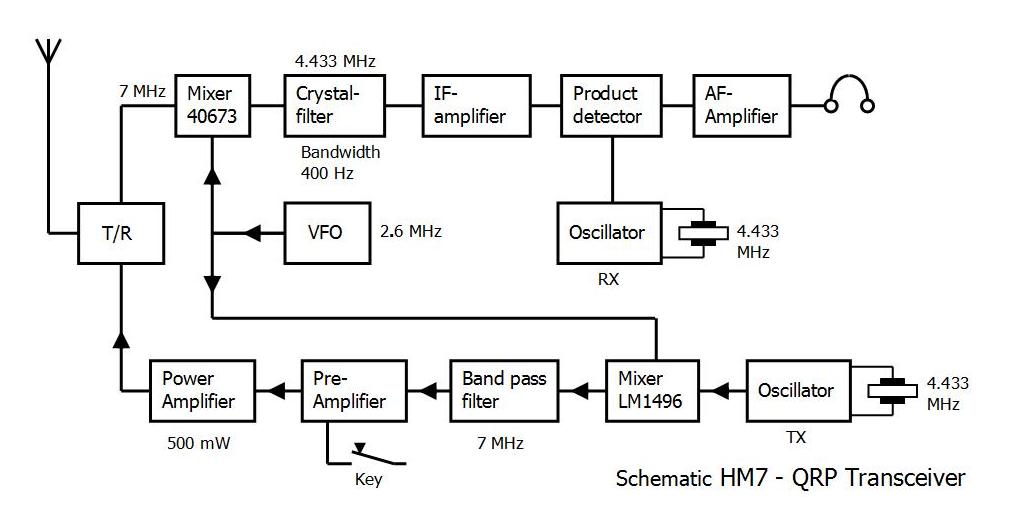
The transceiver tunes a 40 kHz section of the 40 meter CW band.
The power of the transmitter is adjusted to 500 mW.
The selectivity of the receiver is provided by a homemade 3-pole crystal filter of the lower side band ladder type.
The bandwidth is 400 Hz and the rejection of the undesired side band is about 60 dB.
A good working T/R switch switches automatically from receive to transmit by pressing the key.
The receiver is shown in the upper part of the schematic. The front end is is a dual gate MOS-FET 40673 with a single tuned circuit as a preselector.
The IF amplifier has a gain of 40 dB and has no AGC. The gain variation of 60 dB is provided by a manual gain control potentiometer.
The product detector is balanced and has 4 diodes. The BFO injection is provided by the oscillator. (RX) The audio amplifier consists of 4 transistors.
The VFO on 2.6 MHz has an excellent stability because of it’s low frequency.
In the lower part of the schematic, is the transmitter part.
The carrier oscillator is a bipolar transistor in the Collpitts configuration. To adjust the frequency to the center of the i-f band pass it was necessary to add an inductance and capacitance to the circuit.
I use a LM1496 as a mixer to make the signal on 7 MHz. The output of the mixer is applied to a two-pole band pass filter on 7 MHz.
The pre-amplifier is keyed. For the final amplifier I choose a SC1678 because of the high Vce of 65 V.
Even with no antenna connected, the transistor survives time after time. hi
The output network is a half-wave filter.
I don’t use the side tone circuit, because there is an audio tone in the head set with the key down.
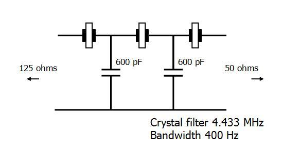
Crystal filter 4.433 MHz Band width 400 Hz
The crystal filter gives the receiver it’s excellent selectivity.
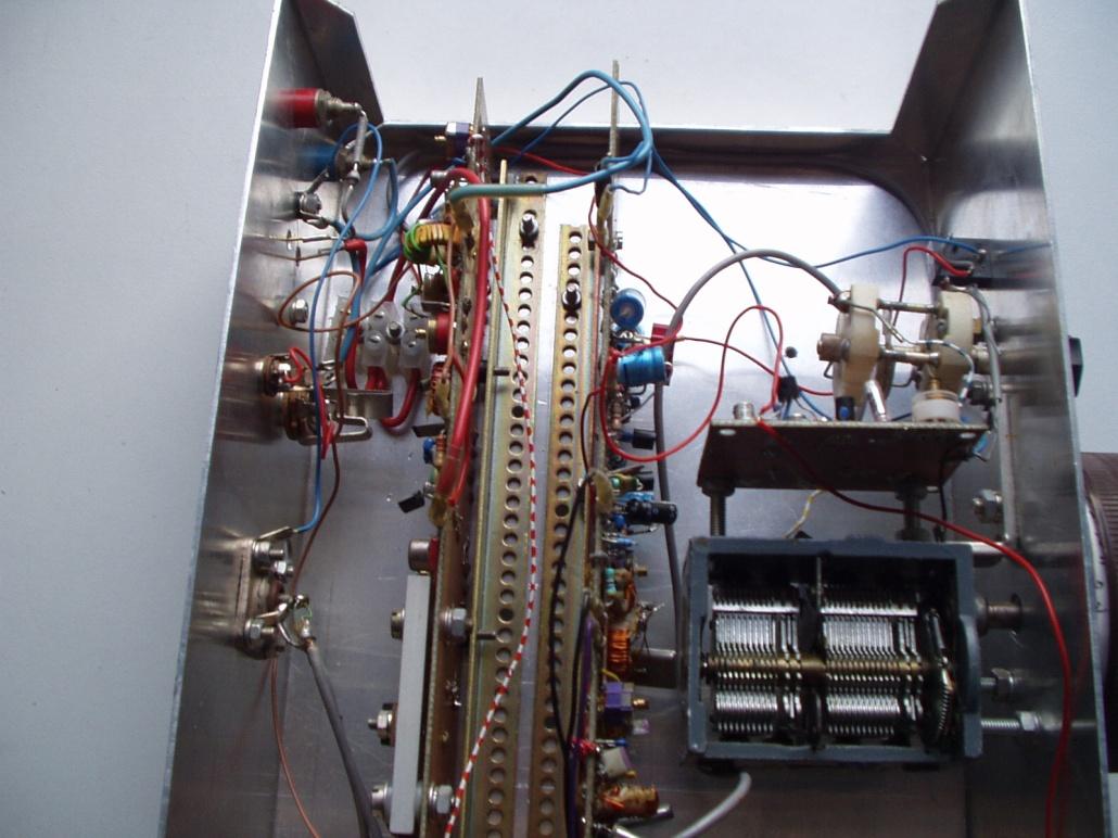
Pictures
HM7 Left the transmitter – Right the receiver
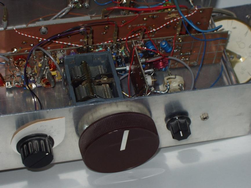
HM7 Front

HM7 VFO
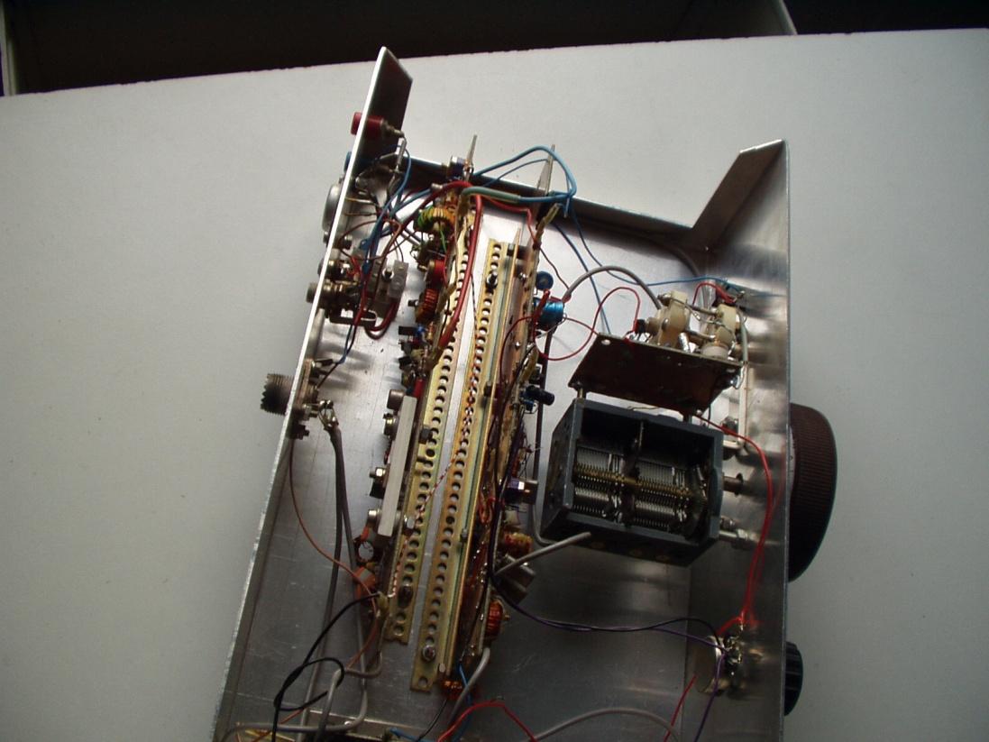
HM7 Overview