HDC10 and HDC14
I have built the HDC14 to make a second homebrew QRP transceiver for CW (Morse code >>) with a minimal number of components and to experiment with working in modules. And I was curious how the combination of a transmitter and a direct conversion receiver would work.
Because it took me a long time to build the first homebrew transceiver, the HM7, I decided to keep this new transceiver as simple as possible, mainly to reduce the construction time.
I call this transceiver HDC14 because it is Homebrew, has a direct conversion (DC) receiver and at first the RIG was designed for 14 MHz. The transceiver is a combination of schematics from ”Solid State Design for the radio amateur”.
Later I changed the working frequency to 10.1 MHz, by changing the crystal and by modifying the low pass filter after the PA. Because of the lack of difficult band filters it took my less than 2 hours to change the frequency band.
I used the HDC10 for many years as the only RIG for 10 MHz and made many QSO’s with only 9 transistors and 2 Watts.
Now the working frequency is changed back to 14 MHz, to use this homebrew transceiver in the homebrew section of the OQRP contest.
Further I reduced the 2 Watt to 500 mW to participate in the VLP class. (Less than 1 Watt)
Layout
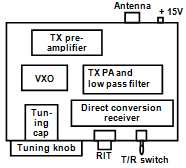
On the front on the left you see the tuning knob and tuning capacitor. In the middle the black RIT knob and on the right the transmit/receive switch.
Below the switch there is the connection for the earphone. In the RIG you see the receiver board at the front.
On the left in the middle the oscillator board and the power amplifier board to the right.
At the back of the transceiver there is the board with the transmitter pre-amplifier and keying circuit. At the back site you see the PL259 plug and the 15V power supply connectors.
Layout – HDC Direct conversion transceiver
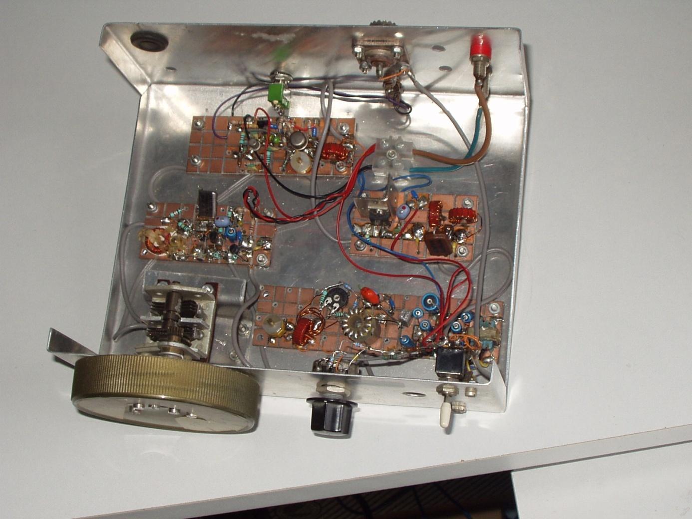
Direct conversion transceiver
Click to enlarge
General schematic
Here you can see how the different parts of the transceiver are linked together. To get a stable frequency the transceiver is equipped with a variable crystal oscillator with a very wide frequency range.
All connections between the 4 boards for high frequency are made with thin coax-cable. With the T/R switch (transmit/receive) the transceiver is switched by hand on transmit or receive. In the receive position the antenna is connected to the input on the receiver and the power is switched to the receiver.
In the transmit position the power is switched to the transmitter and the output of the transmitter is connected to the antenna.
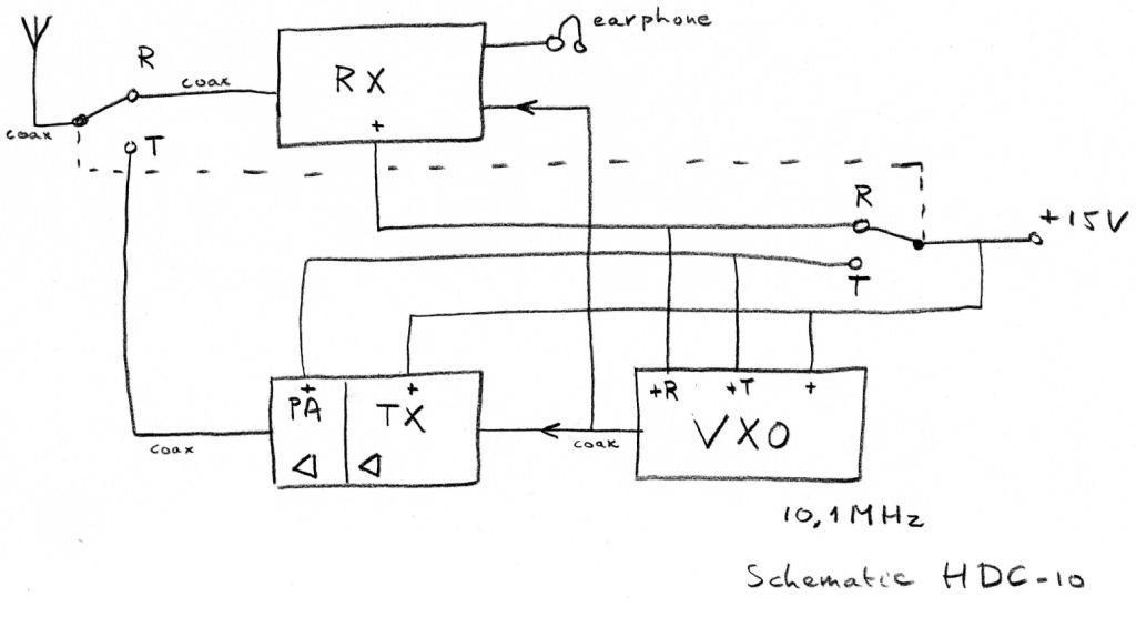
The RIG does not switch automatically from transmit to receive after releasing the key. The RIG has to be switched to receive or transmit manually. The RIG has no side tone. I never built a side tone circuit.
When I started using the RIG I used a straight key. But now I use a keyer with built in side tone.
The variable Crystal oscillator (VXO)
To get a stable frequency I use a variable crystal oscillator. The circuit is special, because it has a wide frequency range. The oscillator can only be tuned down, so the crystal frequency must be chosen above the highest working frequency.
The 2 x 30 pF tuning capacitor is from an old FM receiver and is connected to the oscillator board by a thin coax cable. Because of the shielding effect of the coax cable, the movement of the cable will not influence the frequency.
Frequency range
On 10.1 MHz the frequency range is 10.1 MHz to 10.14 MHz, using a 10.16 MHz crystal.
On 14 MHz the frequency is 14 MHz to 14.090 MHz, using a 14.133 MHz crystal.
The lower frequency of the tuning range is adjusted with a trimmer of 20 pF. The BF245C on the left is the actual oscillator. With the trimmer ”tuning range”” the tuning range of the oscillator can be adjusted.
The BF245C on the right is a buffer stage. The output of this stage is connected with the receiver and the transmitter.
Receiver incremental tuning (RIT)
The oscillator circuit has a RIT (receiver incremental tuning). The receiver can be tuned above and below the transmitting frequency, without changing the frequency of the transmitter.
The RIT circuit is adjusted in such a way, that when the RIT knob is in the upright position, the voltage on the potentiometer is also 4.7V, just as the voltage of the Zener diode.
VCO of the HDC transceiver
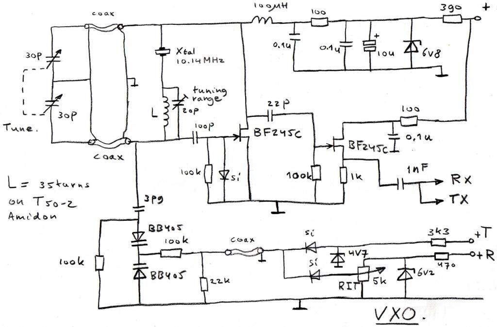
Voltage controled crystal oscillator VXO
In this position the signal of the transmitter is exact on the same frequency as the signal of the receiver.
The oscillator will not start when the RIG is switched on. The oscillator must be started manually by touching the screw of the “tuning range trimmer”.
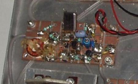
The receiver
The coil at the input, with 30 turns and the trimmer of 70 pF form a band-pass filter, that is adjusted to the frequency of the receiver. With the given value of the trimmer it is possible to adjust to 10.1 MHz or 14 MHz. The 1 turn winding is just a wire running trough the core. In the high resolution photograph below, the wire is visible. It is the orange wire coming from underneath the board and running through the T50-2 toroid. The 5 turns winding is free from the toroid and is positioned symmetrically relative to the toroid, for minimal breakthrough of AM broadcast stations. After the band-pass filter the HF-signal goes to the mixer. The mixer converts the HF-signal into an audio signal. The two diodes in the mixer are matched for the same voltage in forward direction, using a digital multimeter. The coil of 50 mH and the capacitor of 1 µF form an audio low-pass filter. This filter is very important because it determines the selectivity of the receiver. The 3 transistors together with the transformer on the output of the amplifier provide a amplification of about 80 or 90 dB. The receiver is not as sensitive as a commercial RIG, but good enough, when used with 32 ohm earplugs or a sensitive headphone. The receiver is visible to the right.
Click on the picture to enlarge.
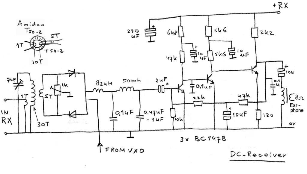
HDC Direct conversion receiver part
The transmitter
The NPN transistors 2N2222 and 2N3053 form the pre-amplifier of the transmitter. The PNP-transistor 2N3906 is the keying transistor.The key is connected between the connector KEY and the ground.The LC-tank of the second stage is tuned to the working frequency of the transmitter. I use the emitter resistor of the second stage to adjust the output power of the transmitter. With a value of 100 ohm the output power is about 500 mW. With a lower value of the resistor, the output power will be higher.The 2SC1678 in the PA was chosen, because of the high collector-emitter voltage. VCEmax = 65 V.The transistor has many times survived transmitting without the antenna. The PA is located on a separate board, together with the low-pass filter.The coils of the low-pass filter are wound on two Amidon T50-2 toroids. The values of the components of the low-pass filters for 10.1 MHz and 14 MHz are both in the drawing above. Pre-amplifier.PA and low pass filter.
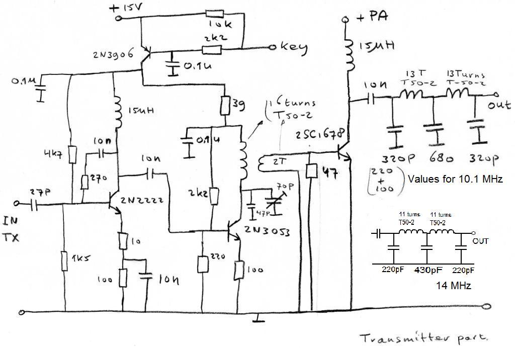
HDC Transmitter part
On the band
The tuning knob determines the transmit frequency. When the RIT knob is in the upright position, the receiver is at the same frequency as the transmitter. By turning the RIT knob to the left or the right, the receiver is tuned below or above the transmit frequency, giving an audio tone. The pitch of the tone of the received signal is adjusted with the RIT.
When I tune the receiver, I want to get my transmitted signal on the same frequency as the received station. I first place the RIT knob in the upright position and than tune the other station with the tuning knob on zero beat. By doing so, the frequency of my transmitter is the same as the frequency of the received station.
After tuning the transmitter, I turn the RIT knob to make the signal of the received station audible, by adjusting the pitch of the audio tone of the receiver. Turning the RIT, only changes the pitch of the received signal, but not the transmit frequency.
The bandwidth of the filter is lower than the pitch of commercial RIG’s with a crystal filter. With the narrowed bandwidth I don’t loose the station during a QSO.
The frequency range of the audio low-pass filter must not too wide. If the bandwidth is too wide, it is very difficult to find the signal of the answering station among the signals of all the stations, after a long transmission, when there is much activity on the band.
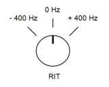
HDC RIT knob
Results
Over the years I made many QSO’s on 10.1 MHz with the HDC10.
Nearly all of the QSO are made within of Europe.
I ran through the pile of HDC10 QSL-cards and came to the following result:
DXCC- countries worked and confirmed (HDC10 only,1992-2003 )
4J, 4U0ITU, DL, ES, F, G, GM, HA, HB9, I, IM,
LA, LX, LY, LZ, OE, OH0, OH, OK, OM, ON, OY,
OZ, PA, UA, S5, SM, SP, TF, TK, UD0, UA9, YL, and YO.
This list shows that the RIG is doing very well al though it is a relatively simple transceiver. Homebrew, QRP and CW (Morse code) is a great combination.
- The lack of a side tone.
- Only hearing the clicking of the key
- The low pitch tone of the receiver
- The need for quickly operating the T/R switch after transmission, to switch to receive
makes working with the HDC10 or HDC14 a unique experience.
I had many hours of great FUN with this simple transceiver with just 9 transistors.

Direct conversion transceiver
Click to enlarge